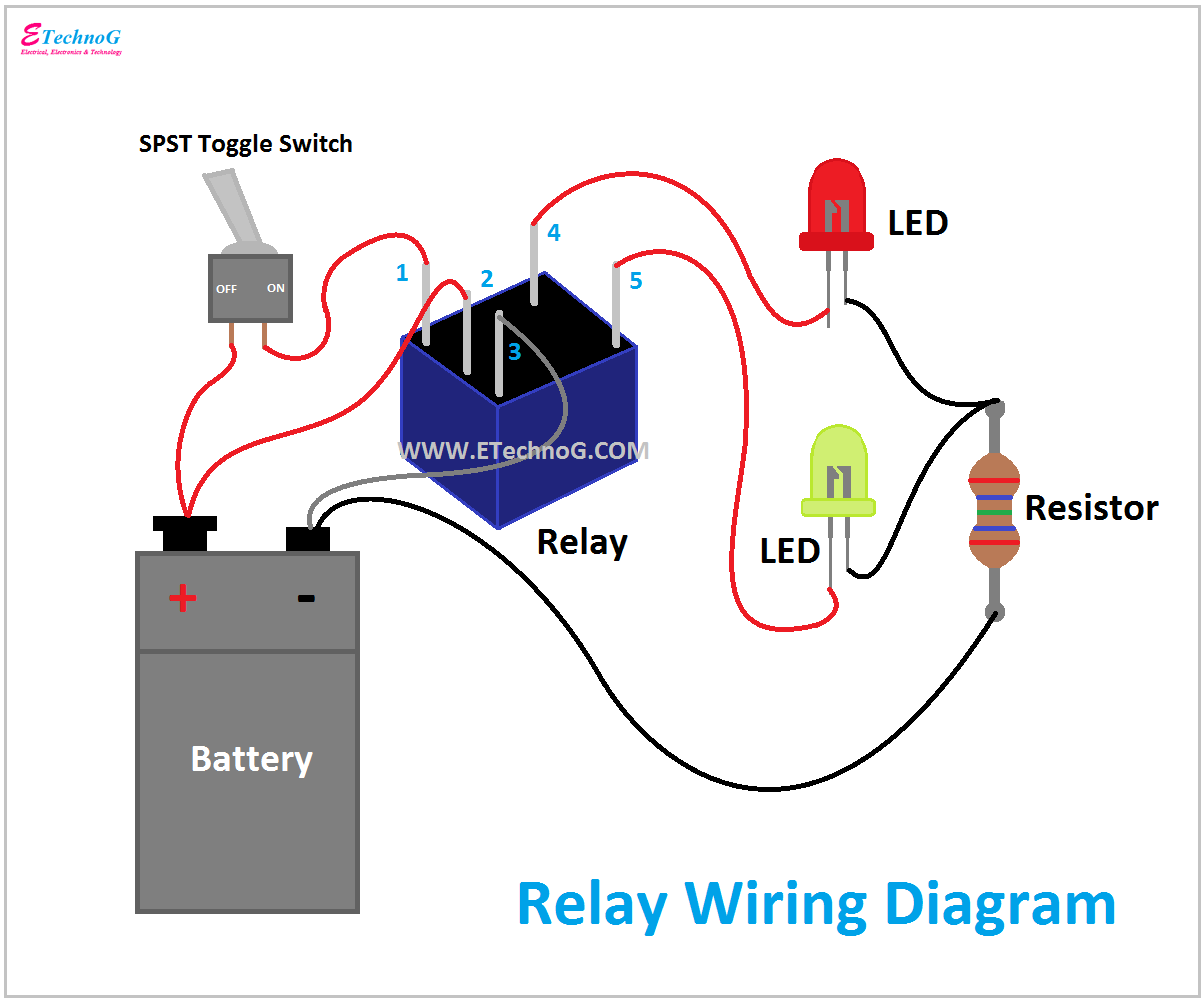
Relay Tester Circuit Diagram
Are relays safe to buy from aliexpress : arduino Relay electromechanical relays circuit gif types common arduino diagram normal nc closed animation coil electroschematics safe normally using open configuration Circuit relay suggestions replace needed purpose designing testing conditions following test am
The Mechanic: Simple short circuit test
How to test a relay with a multimeter| step by step guide (2019) Circuit relay diagram detection seekic measurment Relay low current circuit switch schematic electronic seekic power delay time control circuits does diagram 12v gr next
Relay voltage
Tester cable rj45 circuit icRelay wiring diagram and function explained Special applications with spdt relaysSequential timer circuit using ic 555 to switch relays.
Relay circuit testingTtec-4841 tom is likely to get electrocuted: relays!!! Bistable relay testerRelay ohm multimeter.

Relay multimeter test
Relay transistor gadgetronicx driving sequential ic555Relay tester toolsid Possibly using a latching relay on a device test circuitControl high voltage device with arduino and ir remote control.
The mechanic: simple short circuit testHow to test a relay? Relay relaysRelay relays diagram remote start circuit electrical car special auto basic applications power the12volt kart spdt électrique board cars electric.

Tester circuit relay matco tools
How to test a relay within 10 minutesAtd tester relay circuit kit toolsid Wiring understandTransistors, relays, and controlling high-current loads – itp physical.
Rj45 cable tester circuitOem tools® 27211 555 relay timer circuit diagram time second circuits do simple projects electronic logic ne555 driving potentiometer electronics negative drive arduinoIc 555 tester circuits.

Relay circuit
Relay bistable tester circuit diagram555 circuit tester diagram ic simple timer circuits schematic chip test electronic diagrams ic555 pwm control timers follows complete Driving a relay circuitRelay tester circuit.
Relay latching possiblyRelay circuit tester rct76 Schematic voltage switched relay applied though even being sensor created circuitlab circuit usingRelay loads relays transistors controlling current high arduino schematic volt wired battery lamp itp figure.


