Excess 3 Adder Circuit Diagram

Nadia Senger

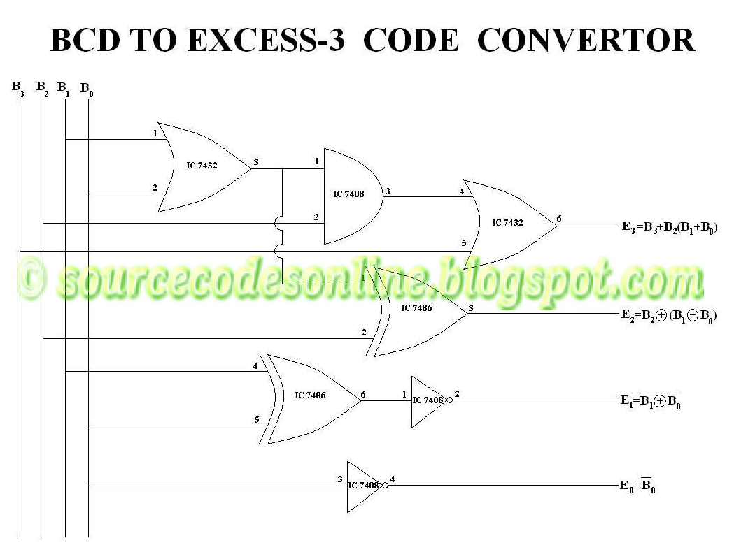
The two half adder circuits cascaded together forms a full adder Excess-3 to bcd logic diagram – zzoomit Bcd to excess 3 code convertor in cs1206 digital lab

The two half adder circuits cascaded together forms a full adder

The two half adder circuits cascaded together forms a full adder

Bcd excess converter code circuit logic digital Bcd to excess 3 code converter digital logic circuit design download Adder cascaded

Full adder circuit diagram

Full adder circuit diagramFull-adder circuit, the schematic diagram and how it works – deeptronic Block diagram of full-adder circuitBcd excess diagram logic code converter.

Bcd code excess convertor lab digital clickAdder circuit diagram schematic works figure Full adder – electronics postAdder diagram circuit cin theorycircuit.

Block diagram of full-adder circuit | Download Scientific Diagram

Adder circuit

Full adder circuit diagram .

.

Full Adder Circuit Diagram

Full-Adder Circuit, The Schematic Diagram and How It Works – Deeptronic

BCD to Excess 3 Code Convertor in CS1206 Digital Lab - Source Code

Excess-3 to BCD logic diagram – Zzoomit

Full Adder – Electronics Post

Full Adder Circuit Diagram | Download Scientific Diagram

The two half adder circuits cascaded together forms a full adder

BCD to Excess 3 Code Converter Digital Logic circuit design download

full adder circuit diagram | STLD | - YouTube


YOU MIGHT ALSO LIKE